Historical Loading Gauges
This page is intended to provide a basic introduction to the great variety of loading gauges in use on the british railway systems at the end of the 19th century.
The topic of loading gauges gets suprisingly complicated. Simplistically there is the structure gauge, which defines the hole, and the loading gauge, which defines the peg, and there is a clearance allowance which ensures the peg doesn't touch the sides of the hole on the way through. Obvious complications include the likes of ensuring there is enough room for doors to open onto platforms. In the very early days, with short 4 wheeled or 6 wheeled carriages and locomotives there was little more to it than that. Even though, to the Great Western Railway's disgust, the track gauge was standardised early on, the structure gauge was not. British lines tended, with the obvious exception of the broad gauge, to have a loading gauge between 9ft and 9ft 3in wide, and between 12ft 9in and 13ft 9in above the rail head in the centre. The actual profile varied even more widely, with the height at the side of the gauge varying between 10ft 6in and 12 ft.
Beyond this there were many local variations, minor and freight lines were especially liable to be built to restricted gauges, as were very early lines. The story, possibly apocryphal, is told of a young executive asking an experienced engineer why one of the early lines, Liverpool and Manchester I think, did not fully comply with the modern passenger gauge, and being told that the engineer supposed no-one had informed George Stephenson!
As the railways developed vehicle length became a factor. A bogie wagon or carriage, for example, overhangs the track on the inside of the turn, and cannot be as wide as a short four wheeled truck. A locomotive with a leading bogie, on the other hand, has a greater overhang on the outside on the bend. Super elevation of the track (outside rail raised on bends) was also a consideration.
In more recent years movement on the suspension has become an important factor in clearance, as carriage suspension tends to be softer and thus carriage bodies more mobile than they once were. As for tilting trains... Modern gauging, especially for passenger stock is based on calculated dynamic 'envelope', not the static measurements used in the steam age.
Standards for railways in the UK are now set by the Rail Safety and Standards Board (RSSB). Unfortunately their documents are no longer available for anonymous access. However if you are happy to register, which is free and automated, they provide an introduction to the complications of gauging in this highly recommended leaflet. It runs to 80 pages, but is well worth reading if you are interested in the subject and wish for an appreciation of the complexities. There is much more - for current gauges the current RSSB document is GERT8073, which can be found from the RSSB web site if you register. It seems to be regularly updated and details vehicle gauges. As of September 2021 it is on issue 4 and 149 pages, and references another dozen or so standards documents... Its very technical and very detailed, as indeed it needs to be.
Returning to the past, its important to understand that the static gauges shown here were rarely universal, even on the individual lines. The major pre-grouping companies were all amalgamations of smaller companies, and it was common for there to be certain routes with restricted clearances in the same way that there were routes with weight restrictions. These were typically listed in general or sectional appendices to the company rule book. Perhaps the most notorious is the "Hastings Line" on the Southern railway which was constructed with undersized tunnels for the already small South Eastern Railway gauge. Consequently smaller locomotives and carriages were required, a problem that has only recently been resolved by reducing all the tunnels on the line to single track. There was also the related issue of weight restrictions on running lines, usually because of bridge strength.
Structure Gauges
Structure gauges are another and possibly even more complex subject. Bridges are expected and do last decades, generations, even centuries, and tunnels are an even more expensive proposition to enlarge. Track is by no means fixed on the track formation, and in the medium term does get moved, and maintaining or increasing clearance from structures is a continuing requirement. Even in these days there is the occasional fatality to remind us of the dangers of leaning out of the window of a moving train.
By 1928 the Board of Trade was mandating quite a generous structure gauge for new construction - 15ft clearance in the centre, which was a good deal greater than most pre group structure gauges. Overhead electrification was definitely in mind. Essentially the same dimensions were in evidence on British Railways drawings of the 1950s. The Southern Railway at least mandated the 15ft clearance on new construction. Oddly the GWR may not have done. I have seen an S&T department structure gauge from the 1930s which is somewhat lower. A drawing from the civil engineers would be more definitive.
Can you Help?
I hope to add further loading gauge dimensions and sketches as I receive them. If you can help with historical loading gauge or structure gauge diagrams please contact me using this form, or if you prefer use Linked In or even Facebook. In general I don't need high resolution scans of the originals since they are normally dimensioned. A mobile phone snapshot is usually fine as long as the dimensions are legible.
Table of Principal Dimensions
| Line | Max. Width | Rail to Platform |
Central Height | Height at 9ft Width |
Eaves Height | Source |
|---|---|---|---|---|---|---|
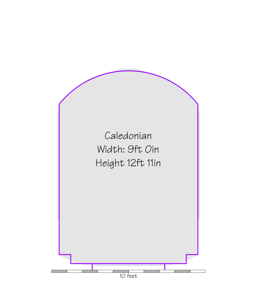
| Caledonian | 9'0 | 2'4.75 | 12'11 | 10'9 | 10'9 | Railway Year Book 1921 |
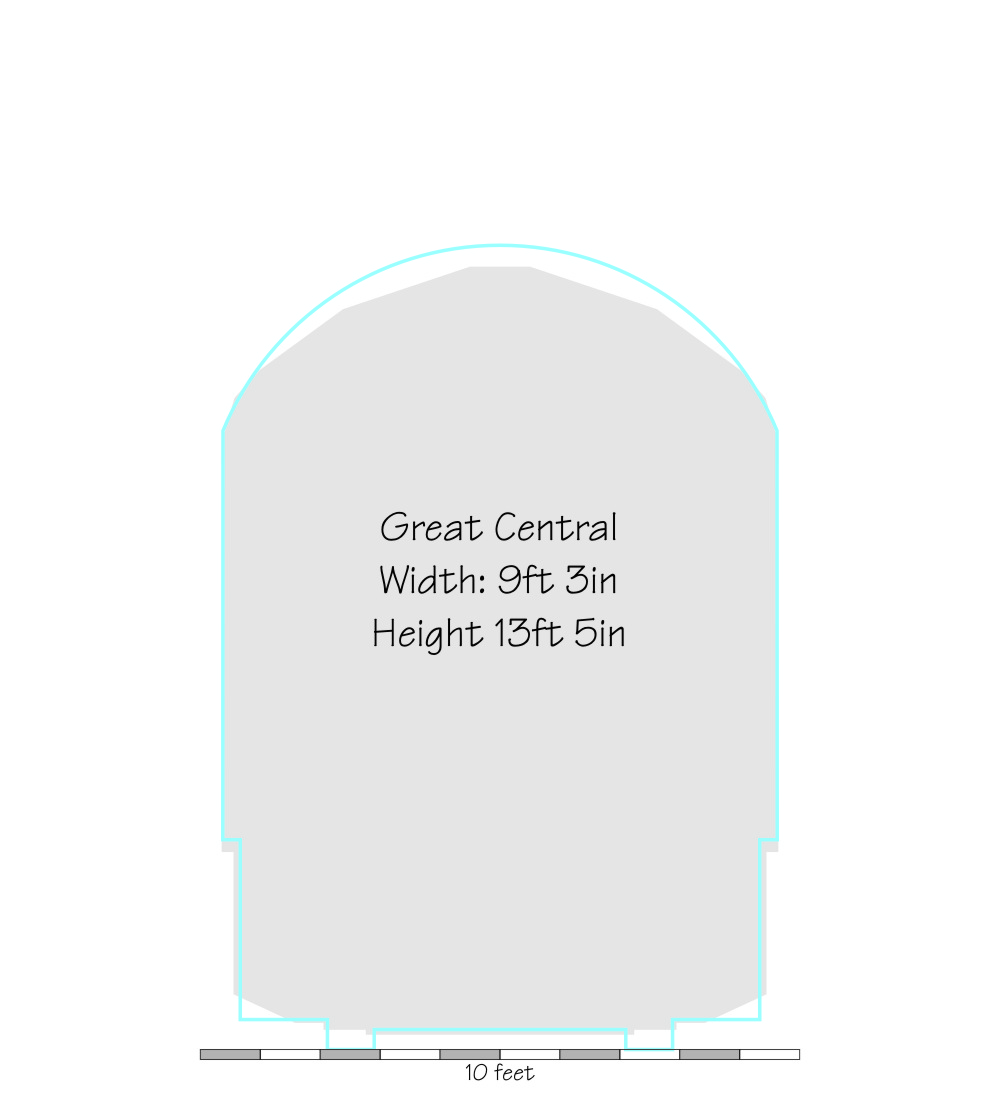
| GCR | 9'3 | 2'4.8125 | 13'5 | 10'7 | 10'5 | MS&L drawing amended GCR 1904 |
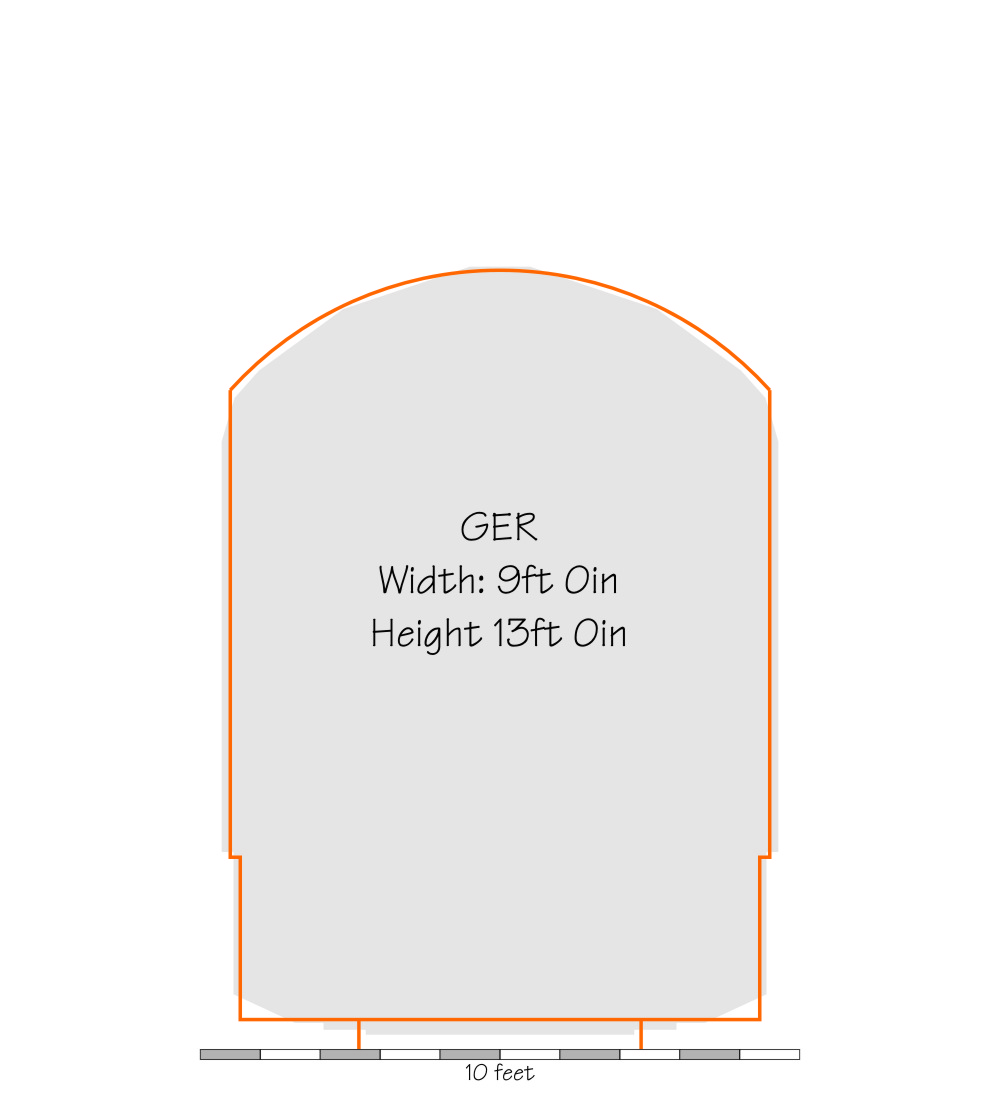
| GER | 9'0 | 2'4.75 | 13'0 | 11'0 | 11'0 | Railway Year Book 1921 |
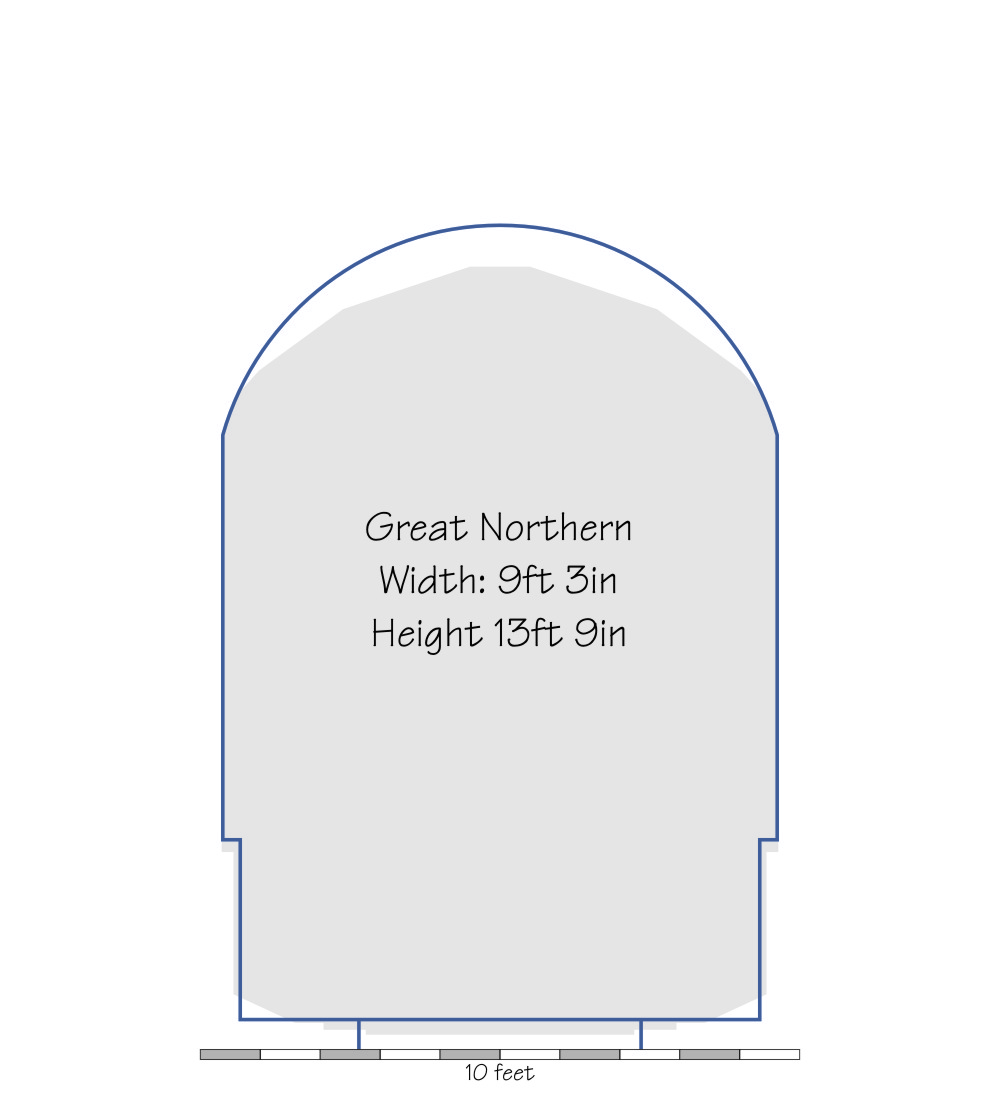
| GNR | 9'3 | 2'4.3125 | 13'9 | 10'7.5 | 10'3 | Railway Year Book 1921 |
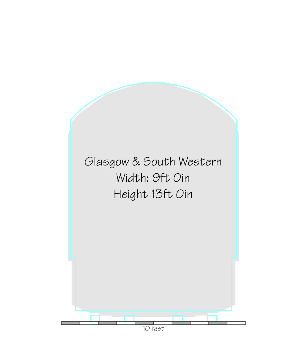
| GSWR | 9'0 | 2'4 | 13'0 | 11'0 | 11'0 | Railway Year Book 1921 |
| GWR Broad Gauge | 11'6 | 2'3 | 15'0 | 13'0.5 | 11'8 | GWR Drawing 1883 |
| GWR 1899 | 9'0 | 2'3 | 13'3 | 11'0 | 11'0 | GWR Engineering document, 1899 |
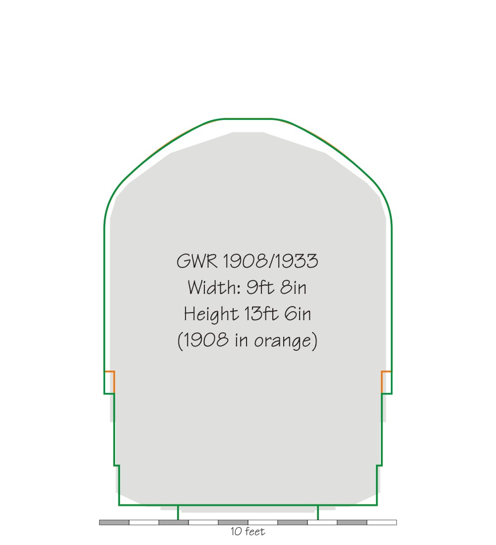
| GWR 1908/1933 | 9'8 | 2'3 | 13'6 | 11'0.375 | 9'10 | GWR Drawings 1908 and 1933 |
| Highland | 9'0 | 2'4 | 12'9.375 | 11'0.25 | 11'0.25 | Railway Year Book 1921 |
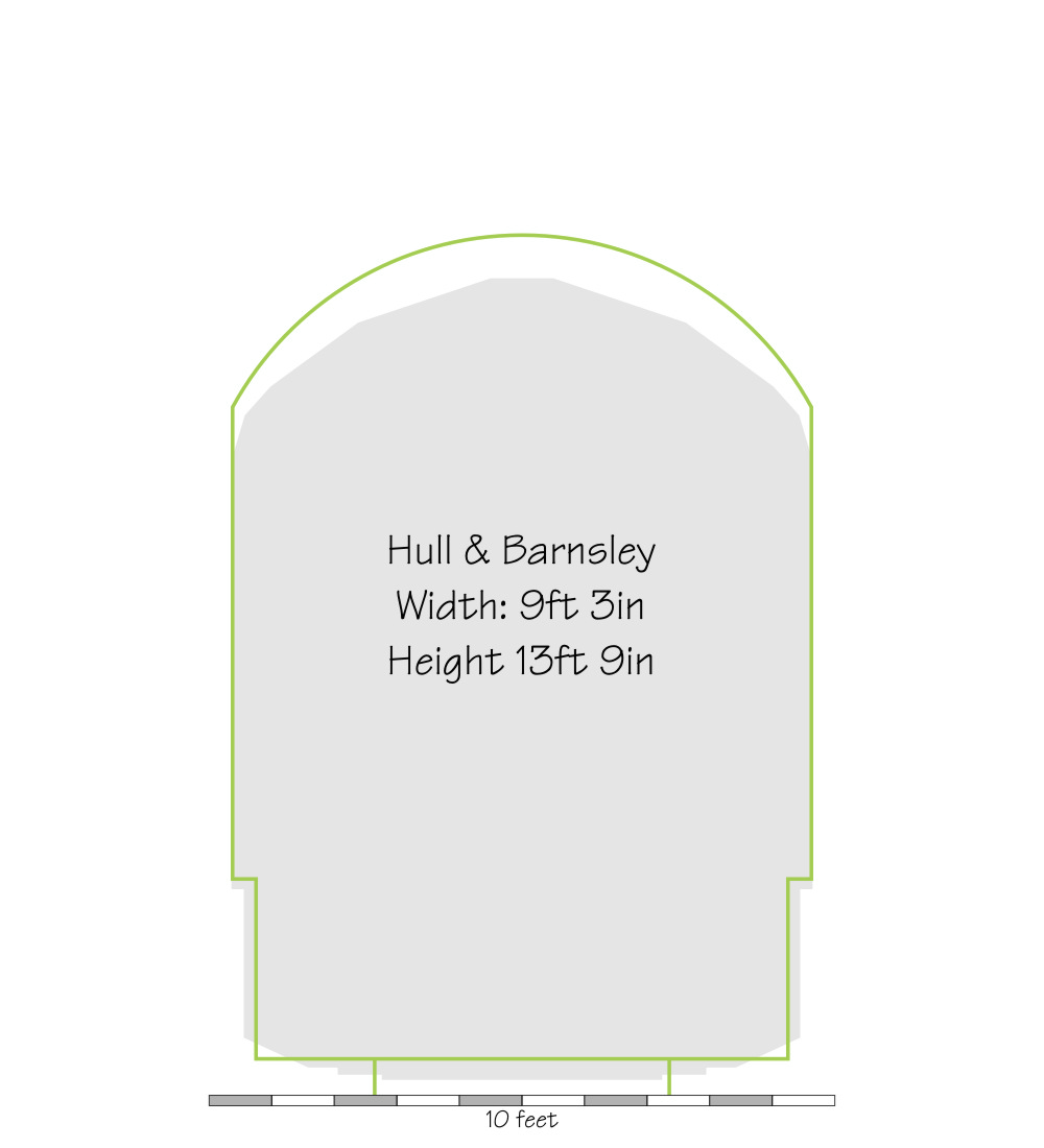
| Hull & Barnsley | 9'3 | 2'4.5 | 13'9 | 11'2.5 | 11'0 | Railway Year Book 1921 |
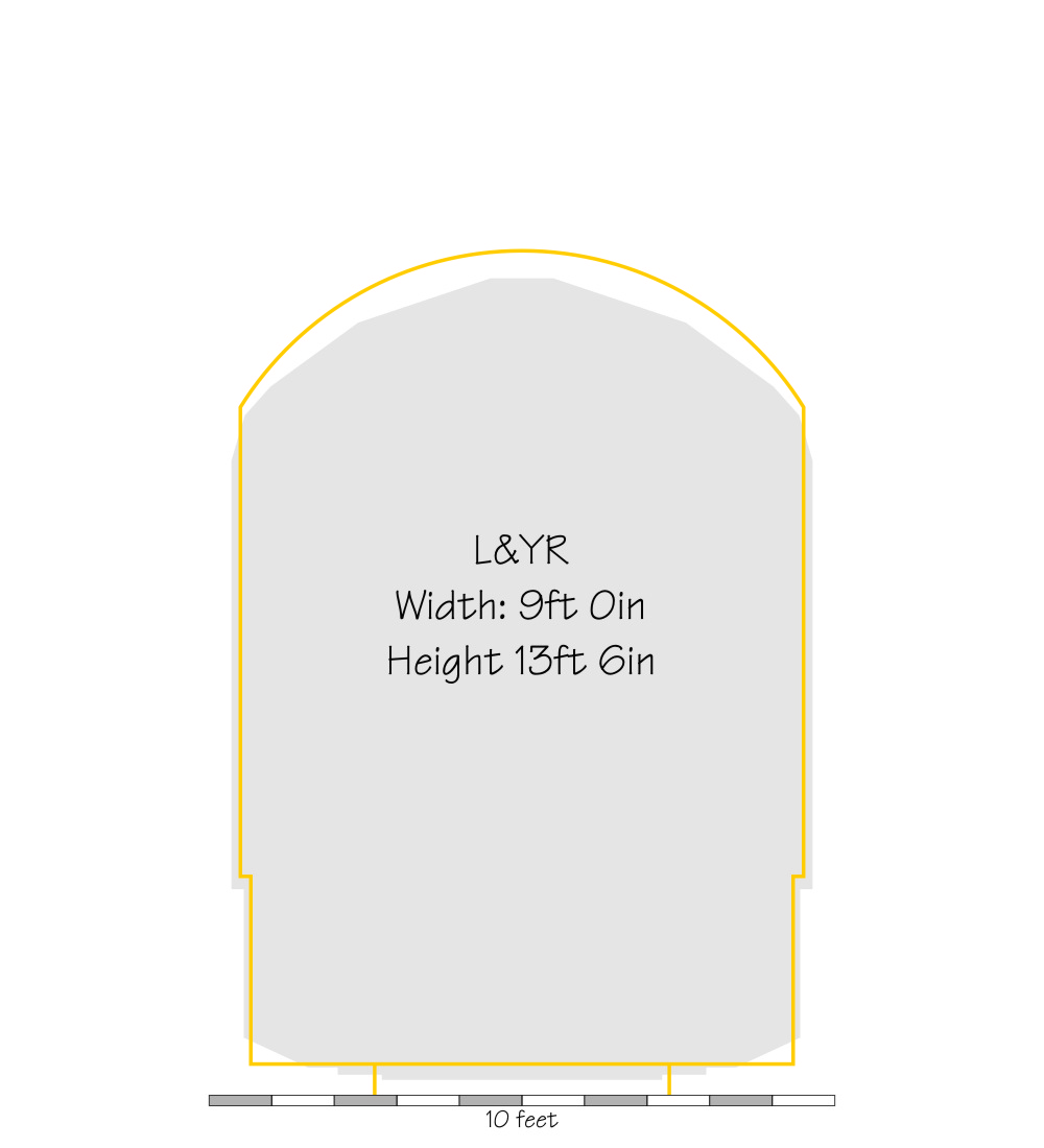
| L&YR | 9'0 | 2'3.75 | 13'6 | 11'0 | 11'0 | Railway Year Book 1921 |
| LBSCR | 9'0 | 2'4.75 | 13'6 | 12'0 | 12'0 | Railway Year Book 1921 |
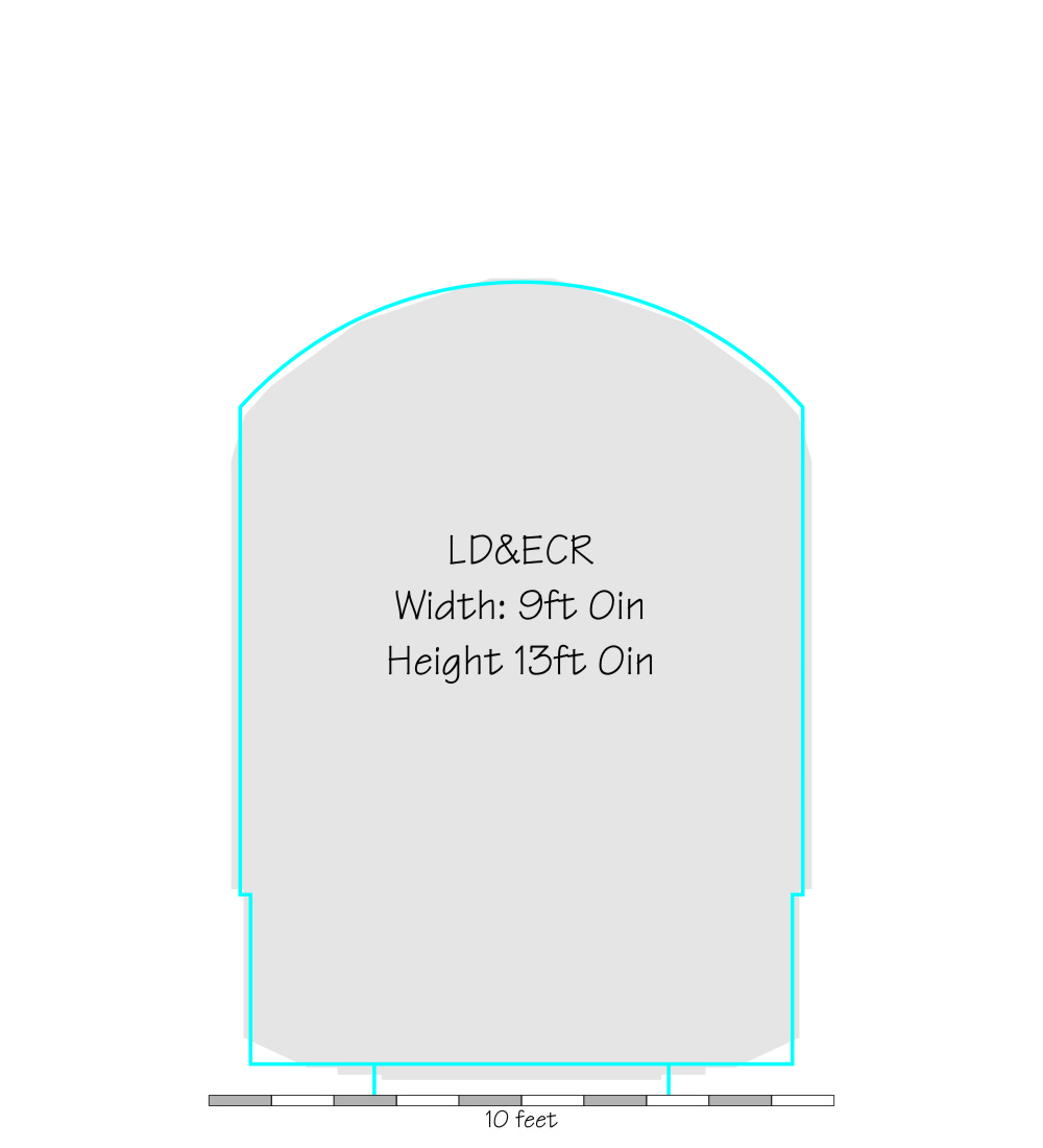
| LD&ECR | 9'0 | 13'0 | 11'0 | 11'0 | Dow, "Great Central" | |
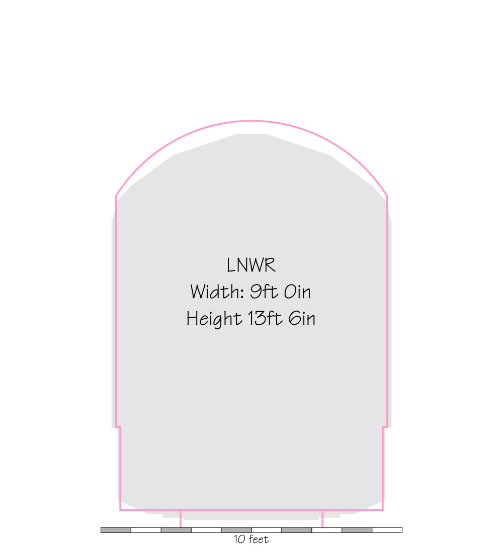
| LNWR | 9'0 | 2'2.75 | 13'6 | 11'0 | 11'0 | Railway Year Book 1921 |
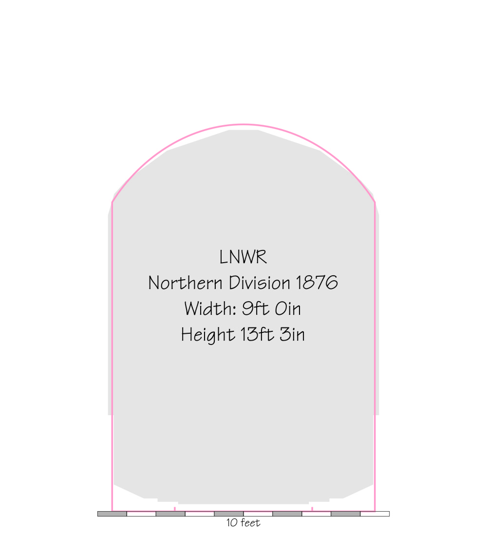
| LNWR Northern Divn. | 9'0 | 13'3 | 10'7 | 10'7 | LNWR Drawing, 1876 | |
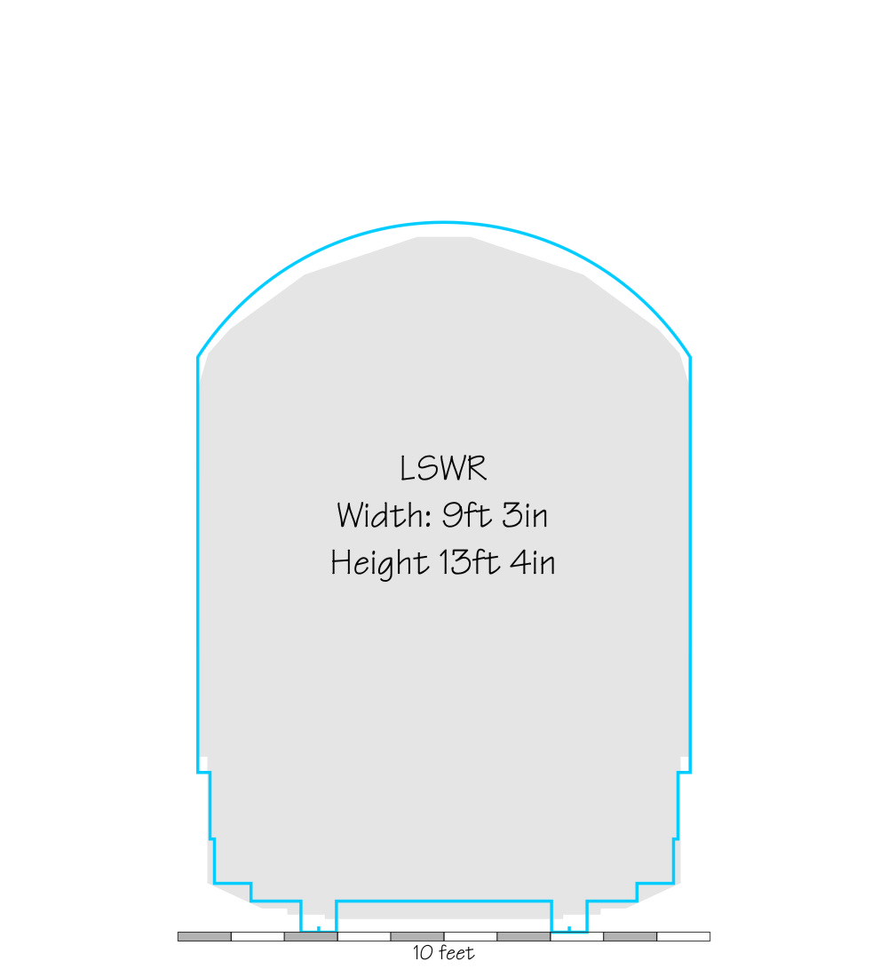
| LSWR | 9'3 | 2'5.5 | 13'4 | 11'0 | 10'10 | Railway Year Book 1921 |
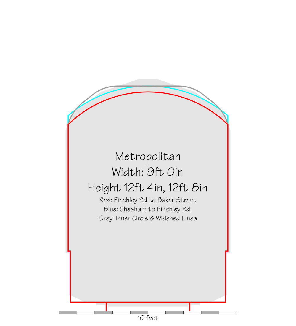
| Metropolitan | 9'0 | 12'8,12'4 | 10'6,11'0 | 10'6,11'0 | Metropolitan drawing, 1892 | |
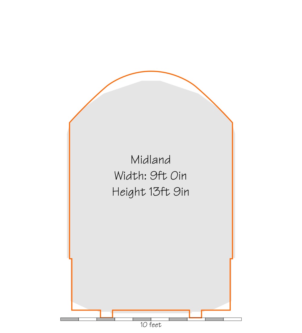
| Midland | 9'0 | 13'9 | 10'9 | 10'9 | MR Drawing 1876 | |
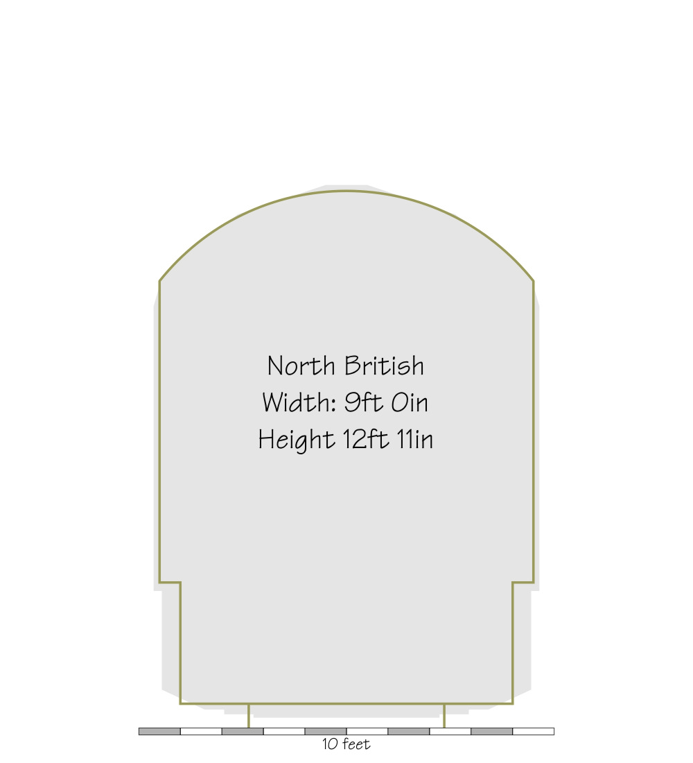
| North British | 9'0 | 12'11 | 10'9 | 10'9 | Railway Year Book 1921 | |
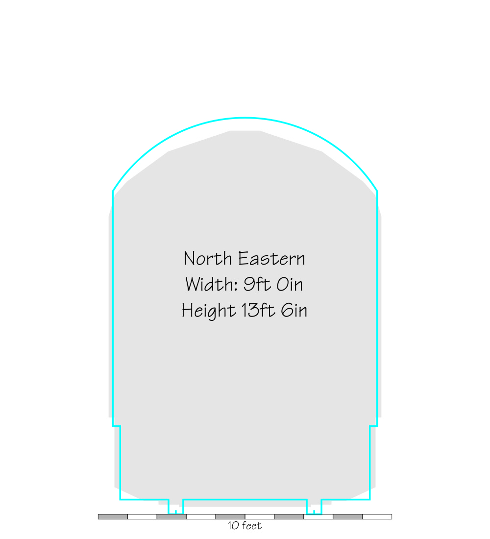
| North Eastern | 9'0 | 2'2.75 | 13'6 | 11'0 | 11'0 | Railway Year Book 1921 |
| North Staffordshire | 9'6 | 13'5 | 10'4.5 | 9'8 | NSR Document, 1882 | |
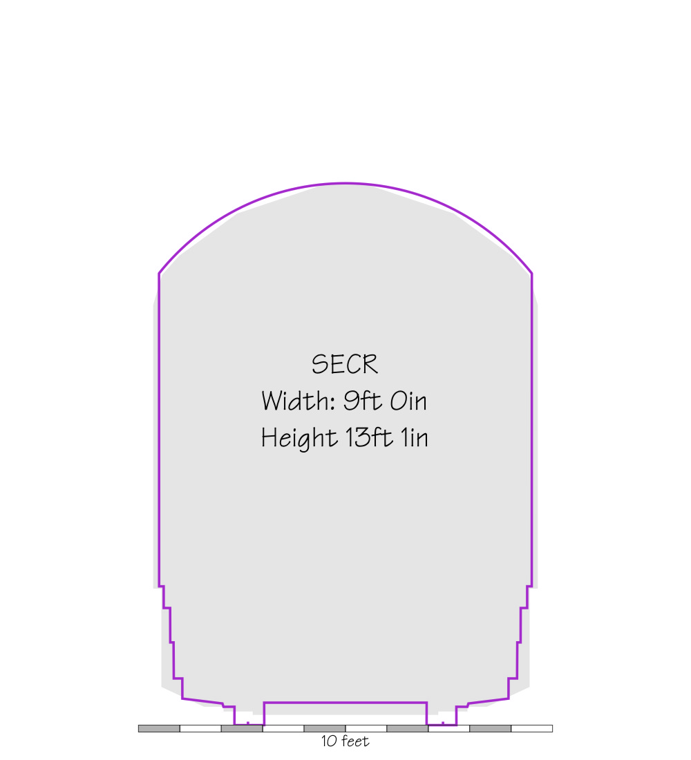
| SECR | 9'0 | 2'4.25 | 13'1 | 10'11 | 10'11 | Railway Year Book 1921 |
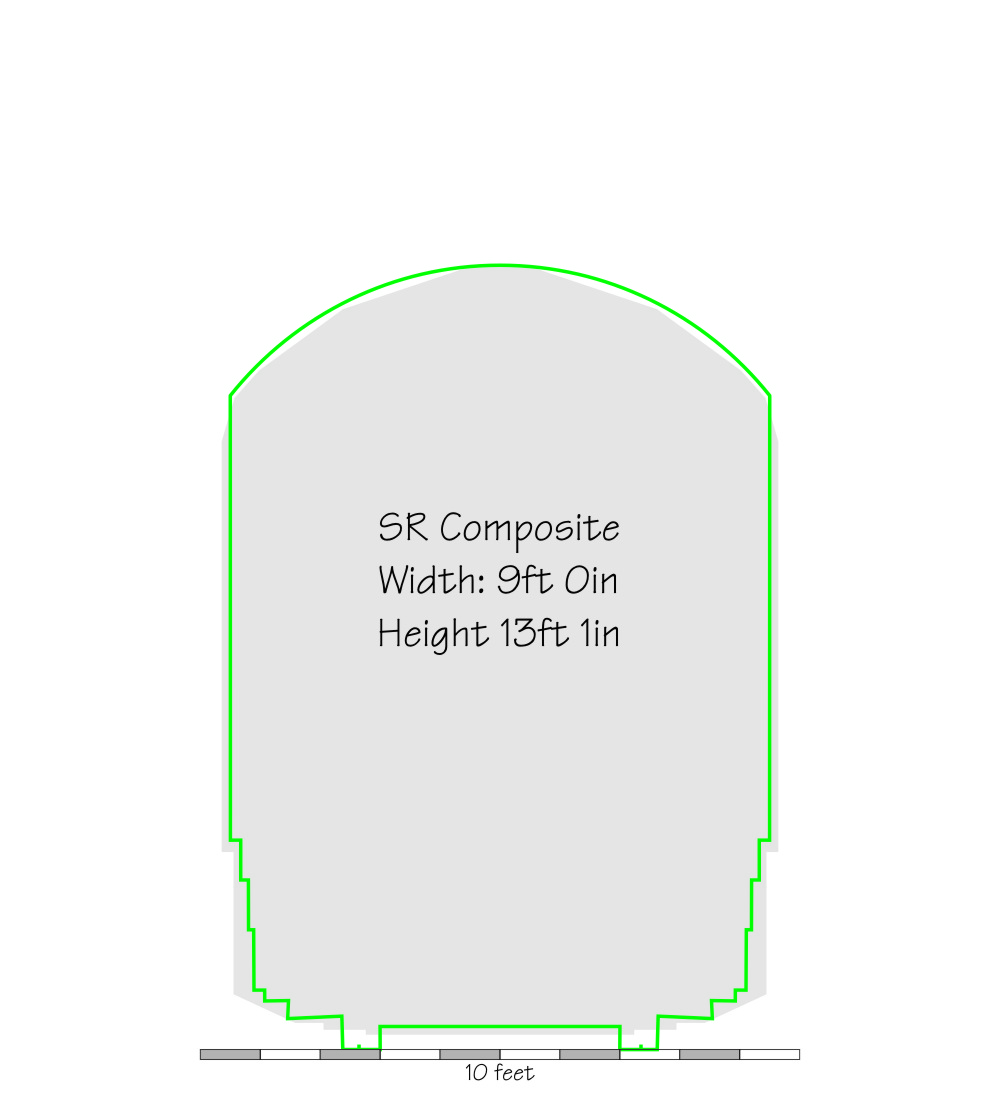
| SR | 9'0 | 2'4.75 | 13'1 | 10'11 | 10'11 | Holcroft: Locomotive Adventure |
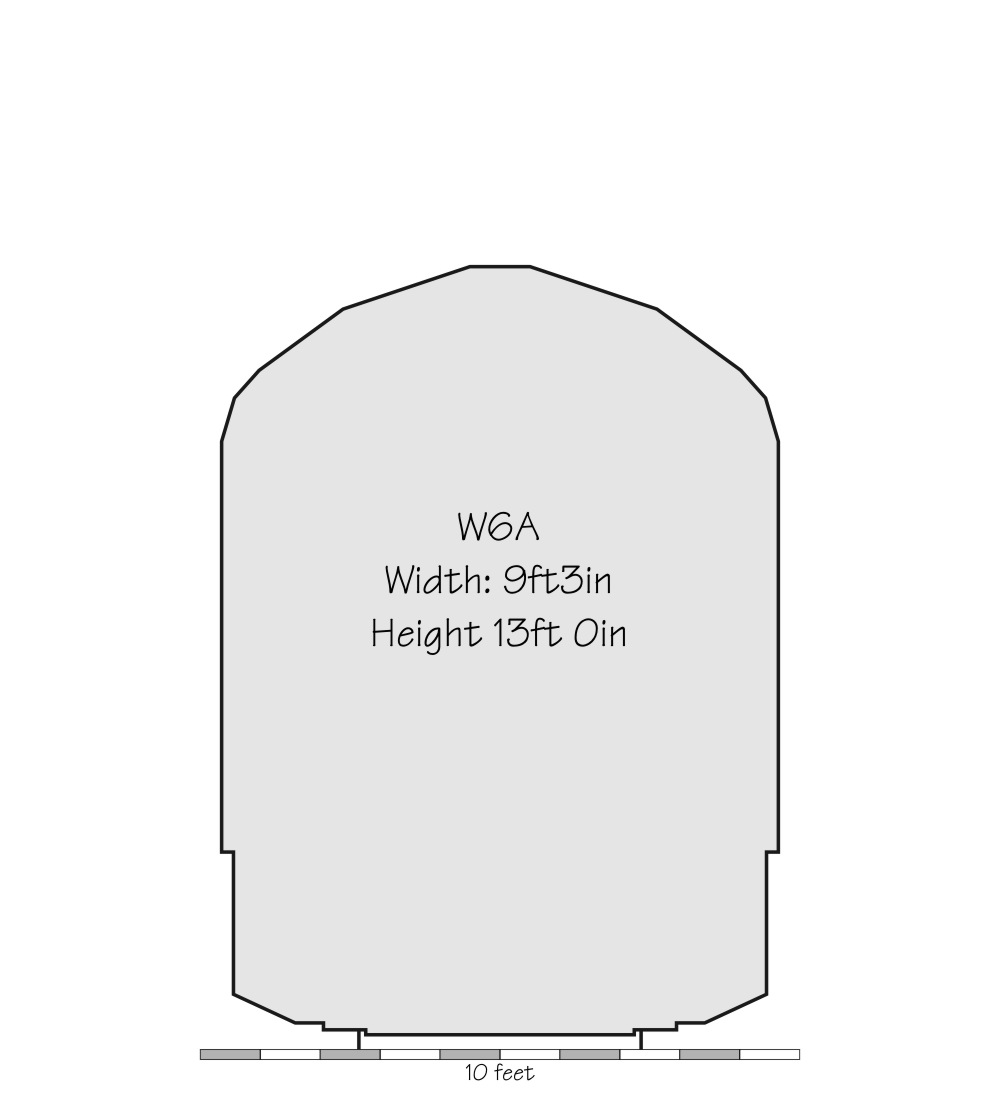
| W6A | 9'3 | 13'0 | 10'7.5 | 10'1 | RSSB GE/RT8073 2015 |
Dimensions shown in a gray cell have been calculated, all others are as listed on official or contemporary drawings, except W6A, which have been converted from metric equivalents.
Comments
Pre Grouping
The study is at too early a stage to draw many conclusions. The subject is complex, and its difficult to understand the gauges chosen for each lines without knowing the history.
GCR and the London Extension
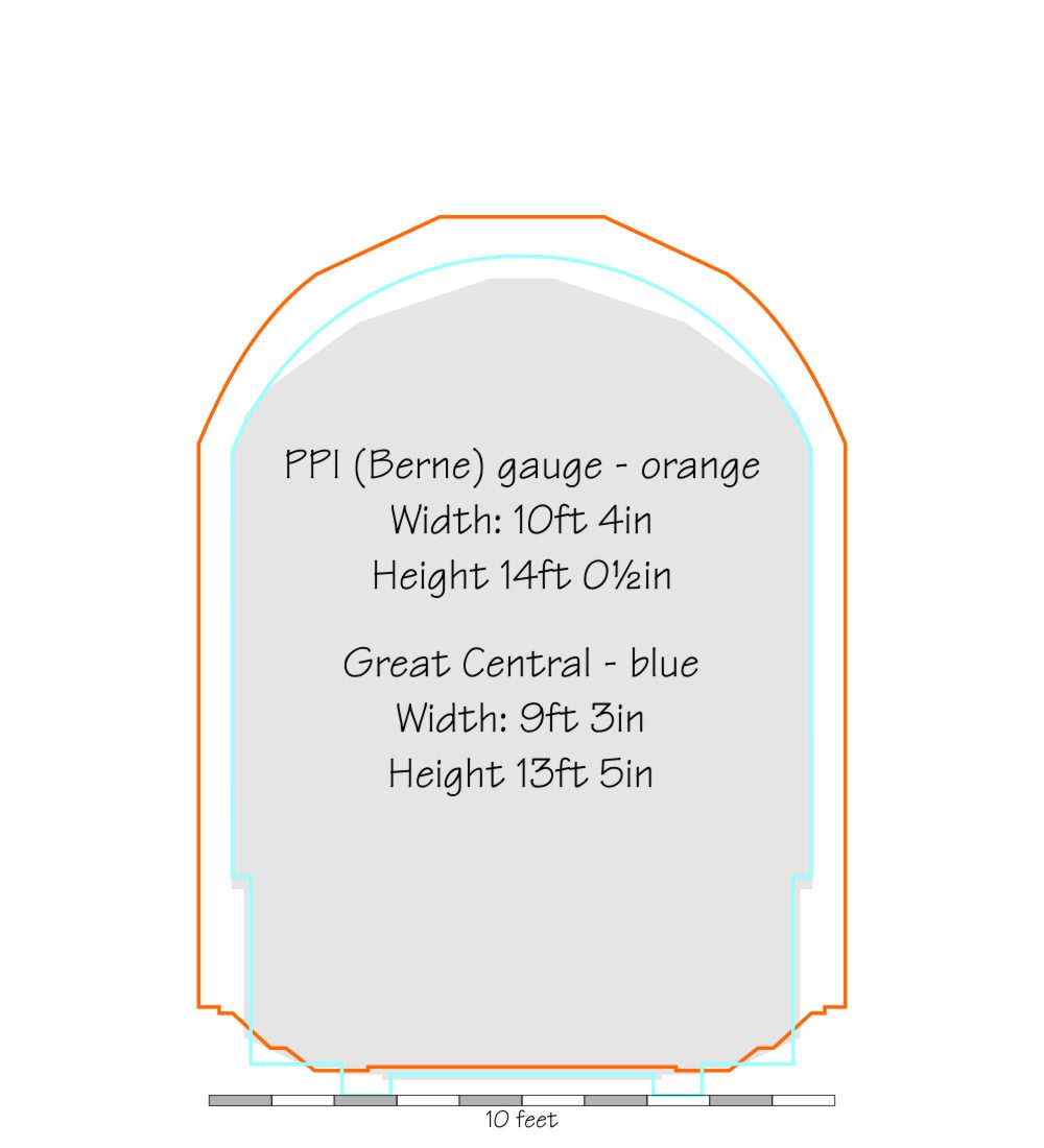
The GCR loading gauge is taken from a collection of drawings from documentation for the GCR London extension. The frequently made statement that this line was constructed to the Berne gauge is a modern myth, since these drawings all clearly show the same gauge as other GCR lines, as, indeed, do the surviving structures. At 9ft 3in wide and 13ft 4in high the GCR gauge was one of the larger british gauges, but still very small compared to the Berne gauge, which was 14ft high and 10ft 2in wide. One should also note that the construction of the London extension commenced in 1894, but the Berne gauge wasn't agreed until 1912. There is a sketch below comparing the PPI (Berne) gauge and the GCR gauge.
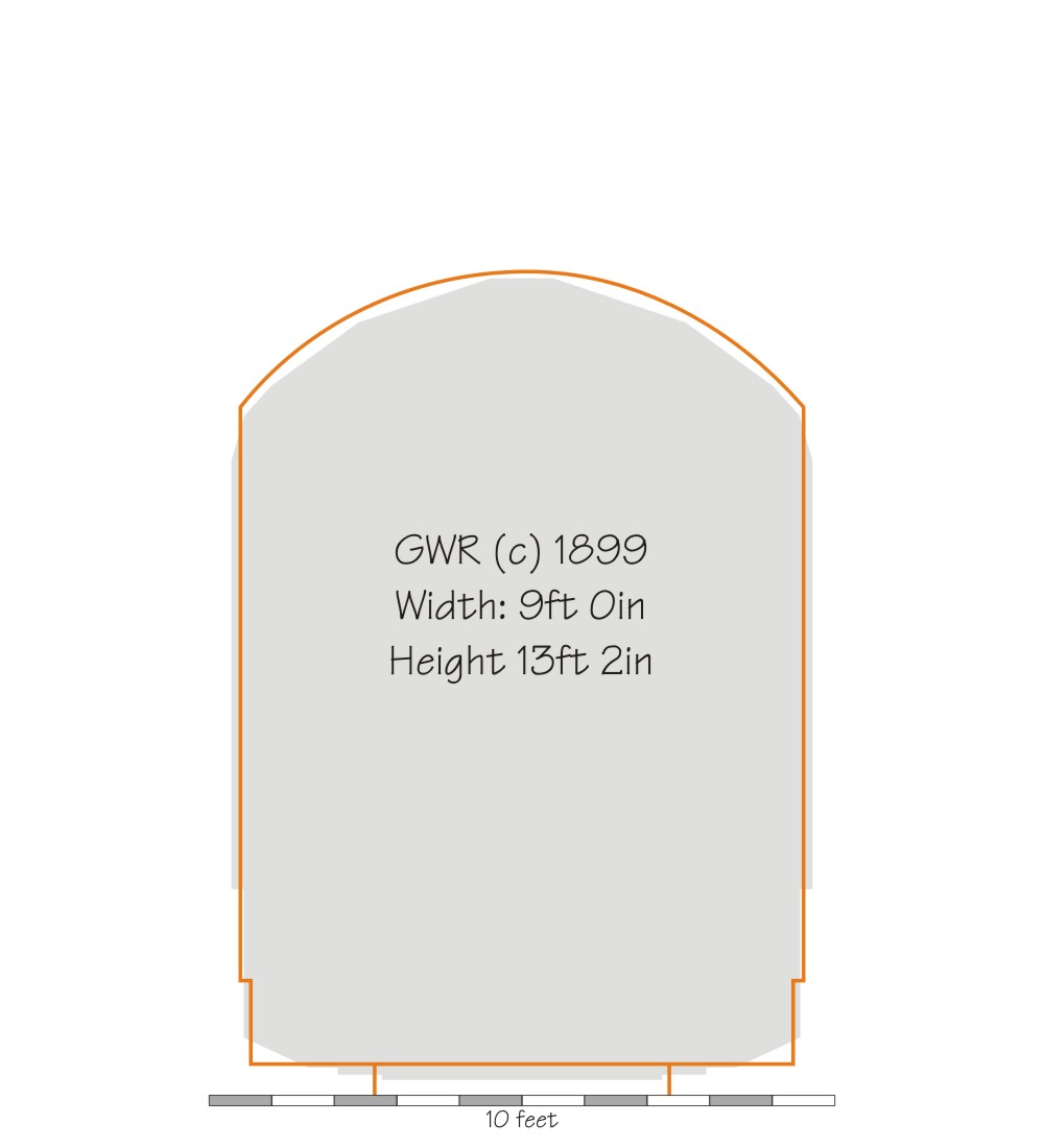
GWR Narrow gauge
The loading gauge on the GWR in the 19th C was not especially large,
at 9ft 0in wide and 13ft 3in high. This gauge presumably dated back
to the early narrow gauge absorbed lines like the Shrewsbury &
Chester and Shrewsbury & Birmingham. At the turn of the 19th/20thC
the GWR appears to have introduced two major changes to the
infrastructure. The first was to build bridge replacements to a 22ton
axle weight limit, instead of the previous 19.5 tons, and the second
was to introduce a new and larger loading gauge. Changes to permit
the new gauge, some 3 inches taller and 8 inches wider, appear to
have been well under way in 1906, according to a paragraph in a
November 1906 "The Locomotive Magazine", and the new gauge seems to
have been formally adopted in January 1908 ( article in a reprint of
the GWR Magazine).
Initially at least the new gauge was only for
use on major routes, and only the new standard 4-6-0s and 2-8-0s were
constructed to make use of the extra height. Smaller classes
continued to be restricted to the old maximum height. Similarly there
were many restrictions on the lines that could be used by the longer
and wider carriages the new gauge permitted.
This gauge was
amended slightly by 1933, and the principle change appears to have
been that the 9'8 maximum width, previously from 5ft to 9ft 8in above
rail height, was changed to start at 4ft 3in above rail height. It
seems possible that this change was made in 1928, since there is
known to have been a GWR 'Maximum Load Gauge' circular issued that
year,the first since 1912.
However there is more to the subject
of GWR loading gauges. In an article in the Great Western Study Group
magazine Pannier, the well respected researcher and professional rail
engineer David Smith states that the Railway Clearing House Coaching
arrangements book of 1888 lists a maximum width of 9ft 8in and
maximum height of 13ft 6in - that of the post 1908 gauge. Another
part of this puzzle is that the well known "Dreadnought" carriages
were built to a 9'8in. width - but they were built from 1903. Wider
coaches were built earlier too. Some, even many brake thirds in the
19thC (diagram T20 of 1880 for example) were 9ft 3.5in across the
guards ducket. These widths were well within the structure gauge, so
ought not to have actually hit anything, but of course the clearance
was there for good reason. Research continues on this apparent
conflict of information.
In any case the popular conception that gauging problems GWR locomotives are experiencing on the modern railway dates back to the broad gauge does not appear to be well founded.
Height overall of the GWR gauge (13ft 6in), although taller than the current gauge, is well within the normal range of gauges found on other lines and several lines were taller.
Width of the GWR gauge at platform height is larger than most, but mainly due to a narrower clearance to the structure gauge. The inner rail to platform clearance on the broad gauge was the same as on the standard gauge, which it had to be for mixed gauge trackwork. The standard width over GWR outside cylinders on the 4 cylinder classes (8ft 8in) was in the general range. The two cylinder classes have wider cylinders (8ft 11in). Its worth noting that in 1901, when Churchward was developing his outside cylinder standard classes, a Dean Single, 3021 Wigmore Castle, was fitted with wooden dummy outside cylinders and used to traverse all the major lines to check clearances.
The main difficulty for GWR locomotives seems to be that platform clearances are being minimised because of the problems of passengers being trapped in sliding doors and dragged between platform and train. Platform clearances are a live issue on the modern railway, and an example of the problems of the platform clearances is shown by a recent RSSB study, T866, on platform edges on the National network. The study used data from the National gauging database, and identified that out of 5,671 platforms included in the study only 384 complied in every respect with the current standards!
Returning to the Great Western, overall width well above platform height, on the other hand, was, post 1906, greater than any other line. GWR locomotives were not built anywhere near the limits of this part of the gauge, but carriages certainly were. A study of the route restrictions in the GWR 'Appendix to the Rule Book' of 1936 shows there to have been a complex set of restrictions for passenger stock, which came in a surprising number of different sizes. 63ft by 9ft 5in stock was not permitted on any other company's lines, nor on a wide selection of GWR routes which appear to be principally routes that were never broad gauge. There has to be a suspicion that this did take advantage of broad gauge structures, with track having been realigned to give greater lateral clearance from bridges and other obstructions. 73ft by 9ft stock was only permitted on a handful of LMS routes and barred from many GWR lines. Smaller widths and lengths of stock had different restrictions, and 63ft 6in by 9ft 3in in stock could be run over much of the old LNWR, some Midland routes, but not over many of the absorbed Welsh lines. 60ft by 9ft stock was much more widely acceptable, with the notable exception of the old SECR lines. A study of gauges used on the GWR and constituents in the 19th Century would further inform this. I hope to address this in future revisions of this document.
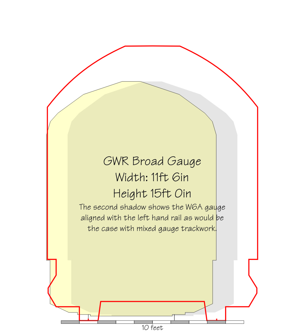
GWR Broad Gauge
There was no standard broad gauge loading gauge either, and the GWR gauge shown here was larger than that of the Bristol & Exeter and Cornwall Railways. As noted above rail to platform clearances were essentially the same as the standard gauge.
In the GWSG Group Magazine 'Pannier', No 16, David J Smith reports that the RCH Coaching Arrangements Book of 1888 gives the maximum stock width on the B&E section as 11ft0in and the maximum height as 14ft9in.
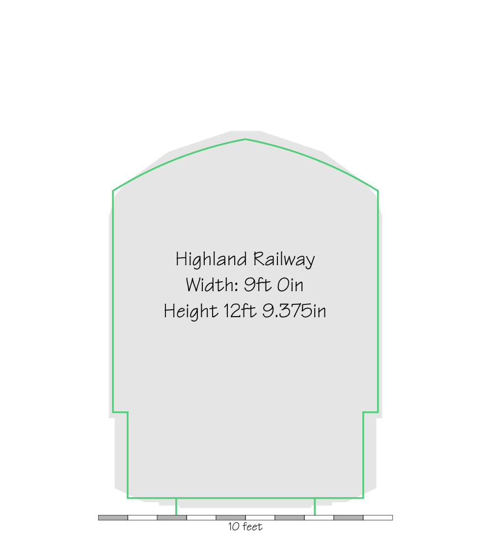
Highland Railway
The Highland Railway gauge shown is quite low, 12ft 9in. This is from the Railway Year book of 1921, but is corroborated by a 1915 Highland Railway drawing I have seen. Yet its documented that Highland Railway Castle, Small Ben and Large Ben classes were 13ft over the chimney top, and according the RCTS the Highland River class was built to a height of 13ft 3.75in, before being cut down to 12ft10in when sold to the Caledonian. Information from students of the Highland is welcomed - requested even!
The Grouping and British Railways
Standard loading gauges after the grouping generally reflected lowest common denominator dimensions, and British Railways did the same.
GWR
The GWR gauge was unique in not changing at the grouping, although many absorbed lines had to have additional restrictions. Even after nationalisation the GWR working gauge was left unchanged and persisted to at least the end of steam, although all new stock after the last Manors complied with the lower BR gauges.
Overhead electrification has exarcebated the issue of clearance for taller GWR locomotives. Surviving stock from other lines had long been cut down to lower composite gauges.
Southern
The Southern Railway's composite loading gauge, as can be seen, was quite small.
LMS and LNER
I have not yet managed to find details for LMS and LNER gauges. I hope to be able to see diagrams next time I am at Kew. Great Northern locomotives are recorded as having been lowered for wider use on the LNER, as were some Great Central classes. Cox, in his book 'Chronicles of Steam' records that Caledonian designs with outside cylinders could not be considered for wider use on the LMS. The reason is obvious when one examines the gauge drawings below.
The British Railways loading gauge was another composite, and so rather small. Considerable effort has been put in to attempt to maximise the gauge within the structures, and the smallest current standard gauge, the W6A freight gauge, is a little wider than many pre grouping gauges. There is much more on the subject in the documents linked above.
Sketches of the Loading Gauges.
The current Network Rail W6A gauge (the smallest of the standard freight gauges) is shown in gray on each sketch to provide a basis for comparison.


Acknowledgements
Thanks to:
Dave Harris/The Midland Railway Study Centre, David
Morgan, Ernest Bate, Harry Holcroft, John Wardle, Neil Hardwick,
Nigel Ogilvie, Tanya Jackson, Jim Summers, Roger Davies, members of
the GWR E-List and others who I have failed to record.
You may also be interested in this related study of Route Availability on British railways in the steam era