Under Construction
15/4/1998 |
|||
| Just ready for the first coat of paint. This view shows the "toe rails" - actually to rest the heels on while sitting out in a relaxed manner and to give something to push out on. | 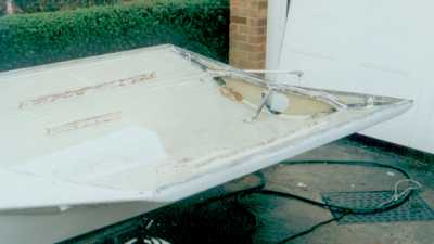 |
The cockpit from above. The big brown patches of microballoons on the floor by the transom are where unidirectional carbon is epoxied into the gantry tube and then fans out across the floor for a solid anchor. | 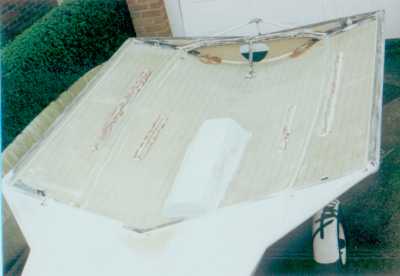 |
| The new beam across the transom to take rudder gantry loads. The circular support beam down to the floor is the only bit of wood on the boat - its glass/carbon on a balsa core - and is actually a piece left over from making the gantry on my last Cherub! | The rudder gantry. The design is conventional but probably not the best for this boat. Ideally the diagonal tube would be at a steeper angle, which I could - on reflection - have managed by running it from the top downwards. | |
|
21/2/1998 |
|||
| I took advantage of a reasonable day to take the hull outside. These pics are with the wings more or less complete. | The wings aren't on their permanent mountings and the angles are not quite correct - they'll be very slightly flatter. | ||
| Aesthetically I think I should perhaps have drawn the chine rising up more towards the bow. | No shortage of room in the crew area! | ||
22/1/1998 |
|||
| The wings complete with support beams. There's not too much room in the garage - not enough for both to be in the extended position. | 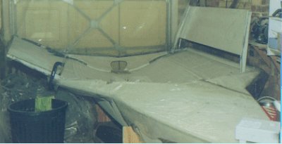 |
This shows the angle of the wings relative to the water. The "gunwhale" at the base of the wing should be the first thing to hit the water, which I hope will be less disconcerting than the tip of the wing with its extra leverage. |  |
| This top view, a few days earlier, shows the port wing in its "fully folded" position for travelling. My father commented that all this folding wings reminded him of his days as a carrier pilot in the Australian Navy! | 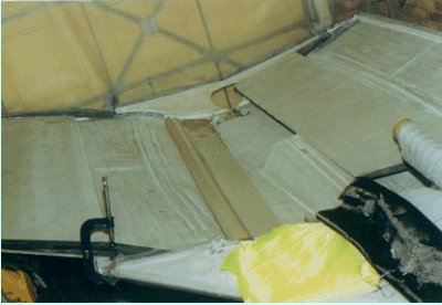 |
A beam in construction - quite hidden by view by the jigs, covered in parcel taps, which are compressing down the curing laminate. | 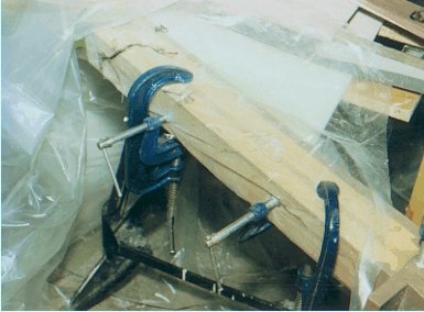 |
| Photos : (c) Jim Champ |
The remaining pictures were all taken at Bloodaxe Boats' workshops on the Isle of Wight
(Click picture for larger version)
28/11/97 |
|||
| The false floor in place. Its beginning to be obvious how clean and uncluttered - and large - the deck area will be. Of course it won't look quite so neat when there are bits of string, toe straps, foot rails and all the other nonsense in there... There's also another 18 inches of width to come with the wings. | 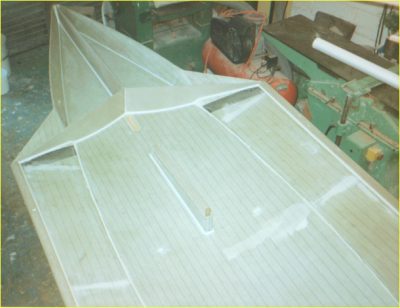 |
||
27/11/97 |
|||
| The False floor, ready to glue down. When the boat is complete this expanse of floor will be broken only by foot rails, toestraps and a low tunnel for the daggerboard case. | 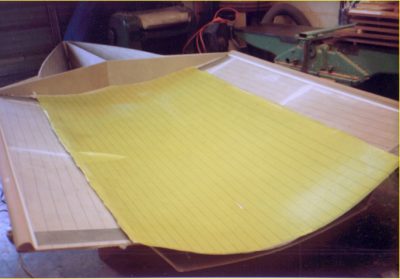 |
The frames under the false floor. | 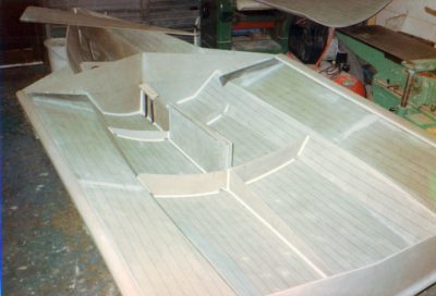 |
| Close up of the daggerboard case area. The case is very long. This is a future proofing exercise to provide the capability to move the daggerboard radically forward - for example if I were to put a jib on. Note the high density foam for the mast foot and the carbon reinforcement down to the spine underneath. | 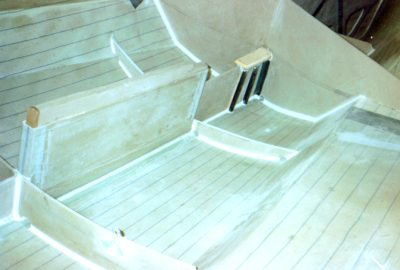 |
Looking aft into the bow tank. The unidirectional carbon reinforcement is for the loads from the prodder. | 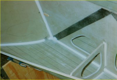 |
| Bow frames looking forward. There will be a false floor above the level of the webbing to brace the sides of the boat and also to permit retrofitting of a spinnaker chute should that ever be desirable. Note the low transverse frames to strengthen the bow in this high load area. Detailed attention to construction like this is the reason why custom-built foam sandwich boats like this have such long competitive lifespans - more than twice that of mass production boats. Of course its also the reason why they cost rather more to buy in the beginning. | 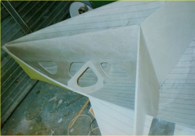 |
||
| Photos (c) Andy Paterson/Bloodaxe Boats. | |||
| A Couple of shots of the hull out of the mould and clearly showing the shape. The patch is where the daggerboard slot will come. | 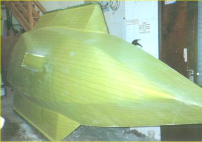 |
 |
|
| Photos (c) Andy Paterson/Bloodaxe Boats. | |||
23/10/97 |
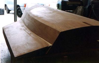
The shell, still on the mould. |
||
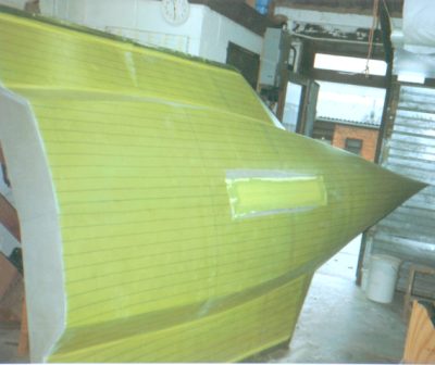
| From above. The fine entry is obvious, and the curvature in the bow sections is observable. | 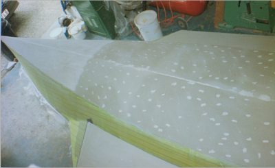 |
A Three Quarters view. The yellow material is peel ply, and the black stripes are trace lines in the 45 degree glass beneath the peel ply. | 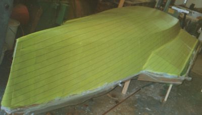 |
| This Bow on view shows the chine line off well I think. You can see that the max. chine beam is well aft, like an 18footer. | 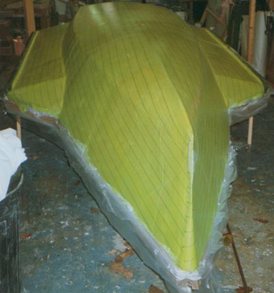 |
The shell from aft. The vacuum bag on the shell for the last layer of glass. | 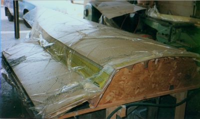 |
| Photos (c) Andy Paterson/Bloodaxe Boats. | |||
11/09/1997 |
|||
| The building jig in the boat builders' workshop. Unusually for a male moulded boat the jig is fully surfaced with ply, rather than just battens. This is so that the inner skin can be vacuum bagged onto the mould. | 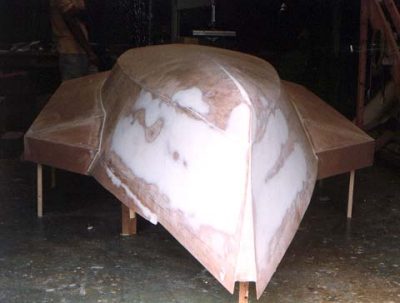 |
 |
|
| Photos (c) Alison Wilde |